What Is a Ground Loop? And How To Diagnose And Fix One
15 min read · Last updated June 8, 2026
What a ground loop is, how it forms in a control panel, and how to diagnose and fix one. A practical guide to grounding, shielding, and EMI for engineers.
You've wired a panel, tested it on the bench, and every signal came in clean.
Then you installed it. Suddenly, the tank's pressure sensor reads a different value every second, even though the tank hasn't moved. At the same time, the temperature sensor reads three degrees high one minute and five the next, but you can't get it to repeat the same number twice.
Nothing is miswired, every component checks out individually, and nothing is broken. But once the panel is connected to the rest of the system, the readings don't make sense.
That's how a ground loop shows up. It messes with your data until somebody figures out the actual problem isn't in the panel at all.
Ground Loop Example
How A Ground Loop Forms
A ground loop forms when a system is connected to ground in more than one way. This creates a tiny potential difference between grounded points where unwanted current can flow. Stray electromagnetic fields formed by current in the loop can disrupt signals in your system.
In this example we'll look at how ground loops can be accidentally or innocuously formed in an everyday scenario. If you're familiar with the idea, please suspend your disbelief and assume that the mixer doesn't have signal isolation.
The shield internally connects to the ground of both instruments.
The Issue
The mixer and speaker are now connected in two ways:
- Through the shielded audio cable
- Through the power cables and shared building ground
It's not immediately clear why this is a problem because the system still performs ideally in theory. But the issue is more from real-world imperfections in electronics and wiring.
The problem starts when unwanted current flows through it.
That current may come from a small voltage difference between the grounds, or from nearby noise the loop picks up.
If current flows through the audio cable shield, it can create noise on the signal.
Again, the loop itself does not automatically cause a problem.
The problem starts when unwanted current moves around the loop and gets into the signal. That current can come from two places: a small voltage difference between grounded points, or nearby electrical noise that the loop picks up like an antenna.
In this audio example, that noise can travel through the cable shield and show up as hum or buzz in the speaker.
Ground Loops Are A Nuanced Topic
Before you read on, we want to emphasize that ground loops are a technical and fairly complex topic that many engineers struggle to understand. While our simple explanations may provide you a base comprehension, additional exploration is likely required for full understanding.
There is no one-size-fits-all explanation or solution to any ground loop question. This is very much a case by case problem that occurs due to a mix of tons of variables on the field. Our guide later in this article should be used to improve your thought process around dealing with ground loops, not as a direct handbook for your problem.
That being said, here are additional references from other authors for a fuller comprehension of the problem. And if learning this subject proves to be too difficult, Blitzpanel can help build your control panel project so you won’t have to worry about ground loops at all.
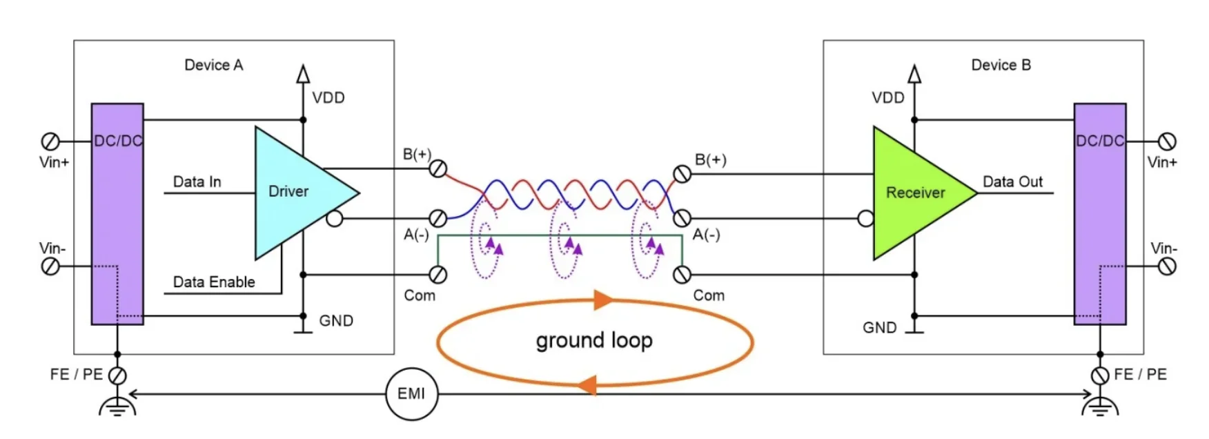
- Ground loops and other pitfalls in shop floor communication (RS Online / DesignSpark)
- Stack exchange discussion on the effects of disconnecting shielding at one side: Stack Exchange: Why does analysis indicate that ground lifts do not fix ground loops?
See how ground loops are made with internals of devices:
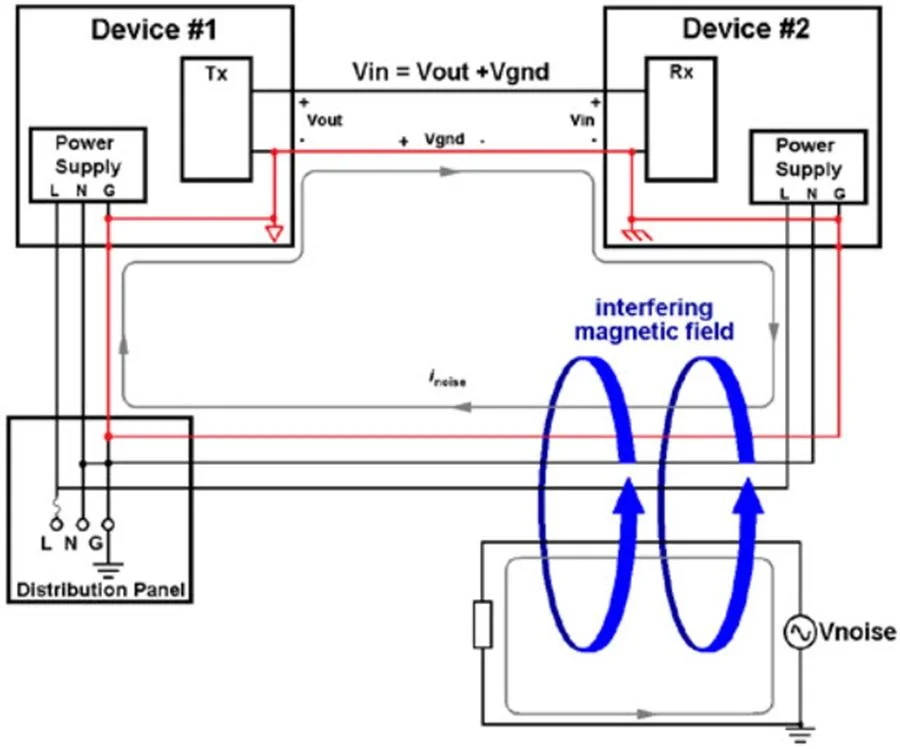
- Breaking ground loops with functional isolation (Analog Devices)
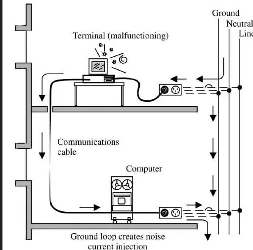
- Field wiring and noise considerations for analog signals (National Instruments)
Why Ground Loops Are Hard To Trace
Before you can diagnose a ground loop, it helps to understand three things: what "ground" actually means inside a panel, why two grounded points can be at different voltages, and where the unwanted current is coming from in the first place.
Ground Isn't One Thing
A control panel can have several connections all labeled ground, and they may eventually tie into the same grounding system. But they exist for different reasons.
- Protective ground is a safety connection. If a live wire touches the panel enclosure, it gives fault current a path so the protective device trips.
- Signal common gives electronic devices a shared reference voltage for measuring a signal. It's the baseline everything else is measured against.
- Cable shields wrap around signal wires and give electrical noise a path to drain away before it reaches the conductors inside.
- Functional ground gives noise a controlled return path without routing it through sensitive electronics.
These are distinct purposes, but in practice, the connections often share physical paths: terminals, enclosure steel, conduit, building structure. That overlap is where things get complicated.
A common example: noise current that belongs on a cable shield finds its way onto signal common instead, because both connect to the same terminal or the same grounding conductor. The shield did its job and captured the noise. But then the noise went somewhere you didn't intend.
This also explains one of the most frequent sources of unintentional loops: many field devices have a single terminal labeled GND that internally bonds both the signal reference and the device chassis together. An engineer wires it as a signal common. The device treats it as a chassis ground too. Now there's a path nobody drew on the schematic. Let's take a look at how that can happen.
Why Two Grounded Points Aren't At The Same Voltage
Schematics make the idea of grounding look simple. For panels and factory floors, it isn't. On the floor, ground runs through wires, terminals, conduit, enclosures, and building steel. None of those connections are perfect. Each one has a small amount of resistance that usually wouldn't appear on a schematic.
When current flows through that resistance, it creates a small voltage drop. That means two points that are both connected to ground may not be at exactly the same voltage. If another wire connects those points, that voltage difference can push current through the new path.
Let's look at this example of a device hooked up to a panel:
Another way to look at what’s happening internally is:
Pay attention to VG1 and VG2. In an ideal world, VG1 should be equal to VG2, which is 0V. However, because of wire impedance, there is a slight voltage at VG1, so a new potential difference, VGND, is created across the ground wire.
Two Sources Of Unwanted Current
So the first source of unwanted current is straightforward: a small voltage difference between grounded points, driving current through whatever path connects them.
The second source is electromagnetic interference, or EMI. Motors, relays, contactors, power supplies, and VFDs all generate electrical noise as a byproduct of normal operation. That noise doesn't need a voltage differential to cause problems. It can couple directly into nearby cables or ground paths and start moving through the loop on its own.
VFDs (variable frequency drives) are the most significant source of this in industrial settings. They work by switching power very rapidly, generating high-frequency noise often in the range of tens of kilohertz. At those frequencies, even a short wire has meaningful impedance, so the noise doesn't behave the way 60Hz current does. A ground path that looks solid on a schematic may do almost nothing to drain high-frequency noise. This is why VFD motor cable shields are typically bonded at both ends: the noise is high-frequency enough that a single-end ground leaves too much of the shield ineffective.
A ground loop in a system with VFDs can act like an antenna, picking up that switching noise and carrying it directly into signal wiring.
Loop Area Matters
One thing that isn't obvious from schematics: the physical size of the loop affects how much EMI it picks up. A larger loop encloses more area and behaves like a bigger antenna. This is why long cable runs — especially between buildings with separate grounding electrode systems — are likely to pick up interference even if everything looks correctly wired.
Frequency Is Your First Clue
Understanding both sources gives you a useful early filter when something goes wrong.
A steady 60Hz hum on a signal usually points toward a voltage differential between two grounded points. The loop is carrying power-frequency current.
Noise that buzzes, whines, or changes character when a motor starts or its speed changes usually points toward EMI coupling into the loop. The frequency and behavior of the noise tells you something about where it's coming from before you've touched a single wire.
That distinction matters when you get to the fixes. The two sources often call for different solutions.
How to Diagnose and Fix a Ground Loop
When Might There Be a Ground Loop?
First, look for signs like:
- The problem appeared after installation
- Noise starts when a motor or VFD runs
- Several signals become noisy at the same time
- The issue appears after a new cable or device is connected
- The panel worked correctly on the bench
A few specific situations account for most ground loops in industrial settings:
- Long signal runs between buildings. Each building has its own grounding electrode system, and those systems are rarely at identical potentials. Pulling a shielded cable between them and grounding the shield at both ends almost guarantees a loop.
- Shielded cables grounded at both ends. This is the single most common mistake. The shield is supposed to drain noise to ground, but if it's bonded at both the panel and the field device, the shield itself becomes a low-impedance path between two different ground potentials.
- Multiple grounding points on the same DC power supply. If a 24V power supply's negative is bonded to ground at the panel, and a downstream device also bonds its 0V to its local chassis ground, you've created a loop the supply current can take.
- VFDs and large motors sharing ground paths with sensitive instrumentation. High-frequency switching currents from a VFD flow back through the grounding system and couple into nearby signal cables.
- Mixing signal grounds and chassis grounds. Signal common (the reference for analog signals) and protective earth (the safety ground) are different things, and treating them as interchangeable creates loops.
How Do I Confirm There Really Is A Ground Loop?
- Check for current on unexpected paths. Use a sensitive clamp meter on cable shields or suspected ground paths.
- Measure between grounded points. Check for AC voltage between the panel ground and the field-device ground.
- Test one connection at a time. When safe, temporarily change a shield or signal-common connection and see if the noise changes.
- Look for what recently changed. A new device, cable, shield connection, or wiring change may have completed the loop.
Note: Never disconnect a protective ground during testing.
Once the ground loop is confirmed, consider which solution below best fits your situation If you are not sure whether the issue is grounding, shielding, or wiring layout, Blitzpanel can help review the panel design and find the likely current paths.
How To Get Rid Of The Ground Loop
There is no single fix for every ground loop. The correct fix depends on where the unwanted current is flowing.
Isolate the Signal
- Isolation lets the signal cross without directly connecting the ground/shield wire.
- Isolated I/O cards and signal isolators are common ways to do this.
Correct the Shield Connection
- Check how the equipment manufacturer says the shield should be connected.
- Don't automatically disconnect one end, but also don't automatically ground both ends.
- The shield connection should match the equipment and the type of noise.
Give Noise a Better Path
- Good bonding, short connections, and proper shield terminations help keep noise out of sensitive electronics.
Separate Signal and Power Wiring
- Keep signal cables away from VFD output cables, motor leads, and other noisy power wiring.
- If they have to cross, try to cross them at a right angle.
Remove Unintended Paths
- Look for connections that were not part of the original design.
- A sensor housing may touch a grounded machine frame. A shield may be grounded at an unexpected terminal.
- Remove unintended connections without removing required safety grounding.
Differential Signaling is Your Friend
- Signals like RS-485 are better at rejecting noise than single-ended signals.
- They still need proper grounding, shielding, and routing.
Design the Ground System Before the Panel Is Built
Ground-loop problems are easier to prevent on a drawing than to troubleshoot on a factory floor. Before the panel is built, decide:
- Where signal commons connect
- Where cable shields terminate
- Which signals need isolation
- How the panel and machine are bonded
- Where VFD and motor cables will run
If grounding, shielding, and signal noise are creating problems in your control panel design, Blitzpanel can help make your panel ground-loop proof.
Conclusion
A ground loop is not automatically a problem.
It becomes a problem when unwanted current flows through that loop and gets into a signal.
That unwanted current usually comes from one of two places:
- A voltage difference between grounded points. Real ground paths have resistance and impedance, so current flowing through them can create small voltage drops. If another path connects those points, current can flow through the loop.
- Electrical noise picked up by the loop. A ground loop can act like an antenna. Nearby motors, VFDs, transformers, and AC wiring can induce current into the loop, especially when the loop covers a large physical area.
The fix depends on which path the current is taking. It may mean changing a shield connection, adding isolation, improving bonding, or moving cables.
The goal is not to remove every ground connection. It is to understand what each connection is doing, control the current path, and keep noise away from the signal.
Blitzpanel can help design control panels that avoid these problems before they reach the factory floor.
FAQ
What is a ground loop?
A ground loop forms when two connected devices have more than one electrical path between them.
If unwanted current flows through the loop, it can interfere with signals.
What is Blitzpanel?
Blitzpanel designs and builds custom electrical control panels. We work with engineers, OEMs, and integrators, providing expert engineering expertise and manufacturing support so panels are built right, documented properly, and delivered fast. Book a call with us here.
Do all ground loops cause problems?
No.
A loop only becomes a problem when enough unwanted current flows through it to affect a signal or device.
Why can two grounded points have different voltages?
Ground connections have small amounts of resistance.
When current flows through that resistance, it creates a small voltage drop. This means two grounded points may not be at exactly the same voltage.
What is the difference between a ground loop and EMI?
EMI is electrical noise created by equipment such as motors, contactors, power supplies, and VFDs.
A ground loop is a path that unwanted current can flow through. It can pick up EMI or carry it into a signal circuit.
Should a cable shield be grounded at one end or both ends?
It depends on the equipment and the type of noise.
Analog sensor shields are often grounded at one end. VFD motor cable shields are usually bonded at both ends.
Always follow the equipment manufacturer's instructions.
Can I disconnect the protective ground to stop a ground loop?
No.
Protective ground keeps people safe during an electrical fault. Fix the signal, shield, bonding, or isolation problem instead.
Why did the panel work on the bench?
The panel was connected to fewer things on the bench.
Once installed, machine frames, field devices, shields, communication cables, and building ground can add new electrical paths.
How do you fix a ground loop?
First, find where the unwanted current is flowing.
The fix may involve adding isolation, correcting a shield connection, improving bonding, moving cables, or removing an unintended path.
What is a VFD?
A variable frequency drive, or VFD, controls the speed of an electric motor.
It does this by rapidly switching power, which can create high-frequency electrical noise.
What is a cable shield?
A cable shield is a conductive layer wrapped around the wires inside a cable.
It helps protect signal wires from electrical noise and gives that noise a path to flow through.
What is protective ground?
Protective ground is a safety connection.
It gives fault current a path to flow if a live wire touches a metal enclosure, helping the protective device trip.
What is functional ground?
Functional ground is used to help equipment operate correctly by giving electrical noise a controlled path.
Unlike protective ground, its main purpose is noise control rather than electrical safety.