How To Make an I/O List for Your Control Panel Project
10 min read · Last updated May 7, 2026
A step-by-step guide to building an I/O list for your PLC control panel project. Covers tags, signal types, wiring configurations, and includes a free downloadable template.
An I/O (Inputs, Outputs) list is a spreadsheet that documents the signals traveling in and out of your PLC (Programmable Logic Controller) project. Engineers take your I/O list and build everything in between to keep your electrical system running smoothly.
Let’s walk through a scenario to get a better idea of what an IO list is, and how it relates to your system.
Simple I/O List Example
Client request: "We have a remote pump house about 200 feet from our operator station. We need a switch at the pump house that turns on an indicator light at the operator station whenever the pump house door is open. The switch is 24 VDC. The light is 24 VDC, draws about 20 mA. We need a panel between them that handles the wiring and protects the circuit."
IO List
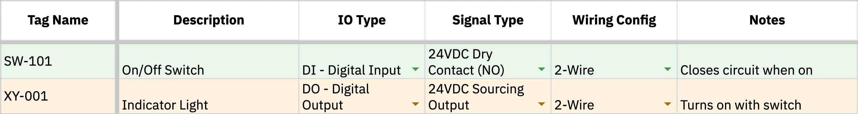
Don’t worry, if this looks confusing right now we’ll break it down!
System Render
Control Panel Build
There are elements of this that may be unrealistic, but this is fundamentally how an IO list is created, communicated, and interpreted.
From just two rows, we know the switch is an input, the light is an output, both use 24 VDC, and both need simple 2-wire connections.
I/O List Breakdown, Column By Column
| Tag | Description | IO Type | Signal Type | Wiring Config | Notes | |
|---|---|---|---|---|---|---|
| Example | PS-101 | On/off Pressure Switch | DI | 24 VDC | 2-Wire | Closes circuit when pressure reaches a certain level |
| What To Put | A short, unique ID for the signal (e.g., PB-101, LS-204, PT-310, etc) | Plain-English description of what the signal does | CommonlyDI, DO, AI, or AO Sometimes COMM, RTD, TC, or HSC Abbreviations explained below | Voltage/current spec (e.g., 24 VDC, 4–20 mA, 120 VAC, etc) | How many wires come out of the device (e.g., 3-Wire (PNP), 2-Wire, Dry Contact, 4-Wire, etc) | Anything else relevant — voltage range, special wiring, interlocks, related tags |
Tag
Tags are your input or output point’s name. They should follow a predictable pattern. Typically you pair a device-type abbreviation with a number. The number depends on the project’s tagging system. Sometimes it’s just a unique ID, but on larger projects it might relate to the tank number, equipment number, area, or loop number
Ex: PB-101 for Pushbutton 101, SV-205 for Solenoid Valve 205, PT-310 for Pressure Transmitter 310
Engineers often follow the ISA-5.1 naming convention standard, but this isn’t strictly necessary. Just pick a scheme and stick with it across the whole list. Inconsistent tagging is one of the most common reasons IO lists get bounced back for cleanup.
Description
A short description of the signal.
Ex: Tank 1 Discharge Pressure, Proximity Sensor NPN, Pump Motor Run
I/O Type
The I/O type describes what kind of signal the PLC is sending or receiving. Control panels typically contain 8 signal types.
The Common 4
- Digital Input (DI): An on/off signal the PLC receives from a field device. The device is either active or it isn't.
- Digital Output (DO): An on/off command the PLC sends to a field device. The PLC is either activating it or it isn't.
- Analog Input (AI): A continuous signal the PLC receives from a field device, representing a measured value like pressure, temperature, or flow.
- Analog Output (AO): A continuous signal the PLC sends to a field device to control it across a range, like telling a valve how far to open.
Specialized Types
- Communication (COMM): A data connection between the PLC and another device, like a touchscreen, motor controller, scanner, or another panel. Common examples include Ethernet/IP, RS-232, Profinet, etc.
- Resistance Temperature Detector (RTD): A sensor whose resistance changes with temperature. The PLC will convert the resistance to a temperature reading.
- Thermocouple Pulse (TC): A TC sensor generates a small voltage based on heat, and the PLC converts that voltage into a temperature reading.
- High Speed Counter (HSC): A fast pulse signal the PLC receives from a device like an encoder, flow meter, or proximity sensor. This is used when pulses are too frequent for digital signals to count.
Signal Type
This column explains the voltage, current, polarity, and contact arrangement of your signal.
Common examples include 24 VDC, 4-20mA, 120VAC, and dry contact. You’ll find this information in your instrument’s datasheet. Here’s a chart that dives deeper into the many types of signals that exist.
| Signal Type | Description | Signal Type Cont. | Description Cont. |
|---|---|---|---|
| 24VDC Dry Contact (NO) | Voltage-free, closes on activation. IO supplies sensing V. | +/-10VDC | Bipolar. Bidirectional control. |
| 24VDC Dry Contact (NC) | Voltage-free, opens on activation. Safety/alarm. | RTD (Pt100) | 100Ω at 0°C. Most common. |
| 24VDC PNP (Sourcing) | 3-wire, sources current. Needs sinking input. Common N. America. | RTD (Pt1000) | 1000Ω at 0°C. Less lead error. |
| 24VDC NPN (Sinking) | 3-wire, sinks current. Needs sourcing input. Common Europe/Asia. | TC Type J | -40 to 750°C. Plastics/packaging. |
| 24VDC Sourcing Output | Sources +24V to load. Most common DO in N. America. | TC Type K | -200 to 1250°C. General purpose. |
| 24VDC Sinking Output | Sinks current from load to 0V. | TC Type T | -200 to 350°C. Best low temp. |
| 120VAC Contact | AC discrete. Legacy/pilot devices. | TC Type E | -200 to 900°C. Highest output. |
| 4-20mA | Standard analog. 4mA=0%, 20mA=100%. Live zero. | HART | Digital on 4-20mA. Config/diagnostics. |
| 0-10VDC | Voltage analog. No wire-break detection. | Pulse/Frequency | Square wave. Flow meters. |
| 0-5VDC | Voltage analog. Certain sensors/legacy. | Relay Contact (NO) | Relay, normally open. Isolation. |
| 1-5VDC | Voltage with live zero (1V=0%). | Relay Contact (NC) | Relay, normally closed. Fail-safe. |
| SSR | Solid state relay. Fast switching. | mV Signal | Low-level millivolt. Shielded cable. |
Wiring Config
This column tells you how to wire your project: the wire count, the power source, and any special cable requirements.
Common examples include:
- 2-wire: The same two wires carry both power and signal. Usually used for loop-powered devices, like a 4-20 mA pressure transmitter.
- 3-wire: The instrument uses three wires: power, common, and signal. Many proximity sensors use this setup.
- 4-wire: Two wires power the device, and two wires carry the signal back to the PLC.
- Dry contact: A simple open/closed contact with no voltage supplied by the device. The panel usually provides the voltage.
- Shielded cable: Special cable to reduce electrical noise. This is common for analog signals, RTDs, thermocouples, and high-speed pulse signals.
Notes
The Notes column is where you capture the small details that often get lost. Useful things to include:
- Signal range (e.g., "0–150 psi" for a pressure transmitter, "0–100 °C" for a temperature sensor)
- Whether a digital input is normally open or normally closed
- Whether a device is loop-powered or requires external power
- Any related signals (e.g., "Interlocked with PB-102 E-stop")
- Spare/future signals you want reserved on the PLC
If you find yourself writing the same note repeatedly, that's a sign it should probably be its own column. If additional help is needed for your electrical project, book a free consultation with Blitzpanel here.
Skip down to the step-by-step guide on how to build your IO list by clicking here.
Why And When Have An I/O List?
By now you might still be wondering: why have an I/O list anyway?
An IO list effectively organizes your electrical system and communicates your needs to control panel engineers.
You probably need an IO list when:
- The project has more than a handful of signals — roughly 10 or more inputs and outputs
- A PLC or other programmable controller is involved
- Multiple parties need to coordinate (engineer, panel builder, electrician, end user)
- The system will be quoted, designed, or built by someone other than yourself
- The project will be commissioned, documented, or maintained by people who weren't part of the original design
- Field devices are spread across multiple locations or skids
- The system is part of a larger facility with existing tagging or documentation conventions
A formal IO list usually isn't worth the effort for small, self-contained projects where a sketch or wiring diagram already conveys the scope. But the moment a project involves a PLC, a panel builder, or back-and-forth between multiple parties, even a rough list of inputs and outputs pays for itself many times over by removing ambiguity at every step. If you’re unclear on how to proceed with your control panel project, book a free consultation with a Blitzpanel engineer.
What You Can Learn From an I/O List - Real Example
Now that we’re more familiar with IO lists, let’s look at a more complicated example:
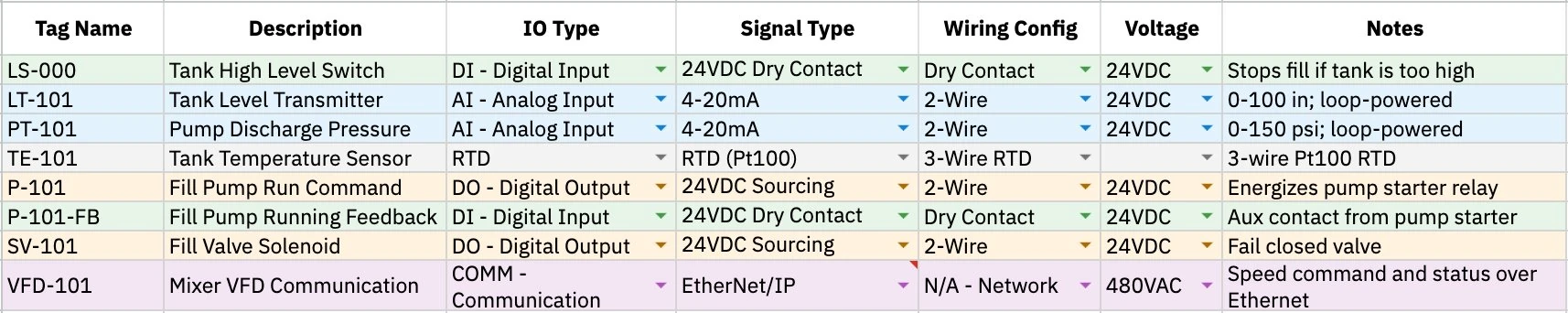
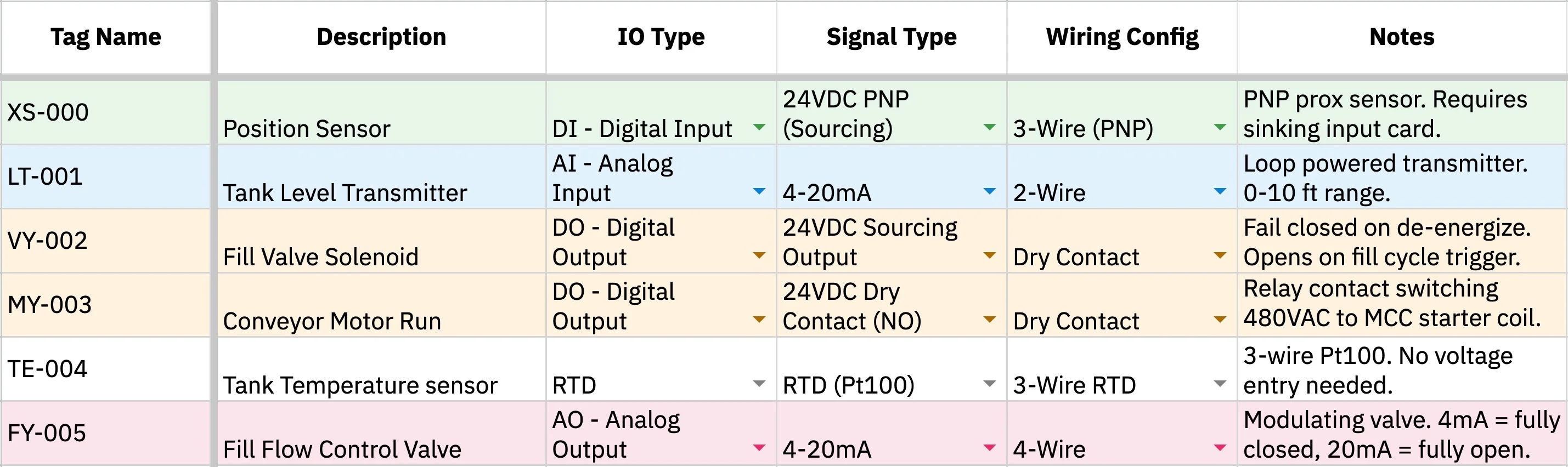
This IO list is for a small tank fill and mixing system. The control panel monitors the tank level and pressure, starts and stops the fill pump, opens the inlet valve, and runs the mixer motor.
Let’s break this apart and see what information about the system we can get from this list:
- First, there are 8 signals total, so this is a smallish control system.
- Parse descriptions and look at the I/O Type for each:
- The tank has a high level switch, which means the system needs protection against overfilling.
- The tank also has a level transmitter, which means the PLC is also measuring the tank level. The type (AI) tells us it needs to be within a certain level.
- The pump has a run command and running feedback, so the PLC can both start the pump and confirm that it actually turned on.
- The pressure transmitter is on the pump discharge, so the system is likely watching pump performance or checking for pressure problems.
- The valve note says fail closed, which tells us the valve should close if power is lost.
- The tank has an RTD temperature sensor, so temperature matters to the process.
- The mixer has a COMM signal, which means the PLC can send commands and read status over Ethernet.
From the list, we can build a simple picture:
The PLC opens the fill valve, starts the fill pump, watches the tank level, checks pressure, monitors temperature, and controls the mixer. If the tank gets too high, the high level switch stops the fill.
As an added note, let’s look at what happens to your I/O list after it’s taken in by a panel shop like Blitzpanel:
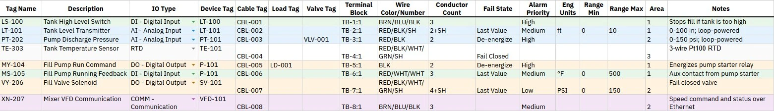
For this example, most of the columns explained above were collapsed to see the fields that shops might add.
The original I/O list usually tells us what signals exist and how the system is supposed to work. The panel shop then adds information that helps turn that list into something that can actually be built, wired, and tested.
For example, Blitzpanel adds columns that help answer build questions at a glance:
What device are we talking about?
- Device Tag gives each field device a clear name, like DEV-001.
- Load Tag marks powered equipment like motors, pumps, or heaters.
- Valve Tag marks valves so they are easier to find.
What cable am I looking for?
- Cable Tag identifies the cable connected to that device, such as CBL-001.
- Wire Color/Number shows which wire colors or wire numbers should be used.
- Conductor Count tells how many wires are needed in the cable.
How should the system treat the signal?
- Fail State tells what the device should do if power or control is lost.
- Alarm Priority shows how serious an alarm is when something goes wrong.
- Engineering Units show the measured unit at a glance, such as ft, PSI, %, or °F.
- Range Min/Max shows the low and high values for analog signals.
Where does it belong?
- Area groups devices by location or part of the system.
These columns make the I/O list more useful for the people building the panel. The panel shop can see what cable it uses, where it lands, how many wires are needed, and how it should behave.
Note that these extra variables aren’t something you typically need to worry about for your IO list, they’re just extra diligence panel shops do to cut all loose ends.
Make Your Own I/O List - Final Summary
At first glance, an I/O list can look intimidating. Dozens of columns, abbreviations, and signal types you may not recognize yet. Don't let that stop you. Fill out what you know and leave the rest. The list builds itself as the project comes together.
The best way to understand it is to walk through one!
Step 1 - Format
Format your own spreadsheet using the fields discussed earlier, or use Blitzpanel’s free template here.
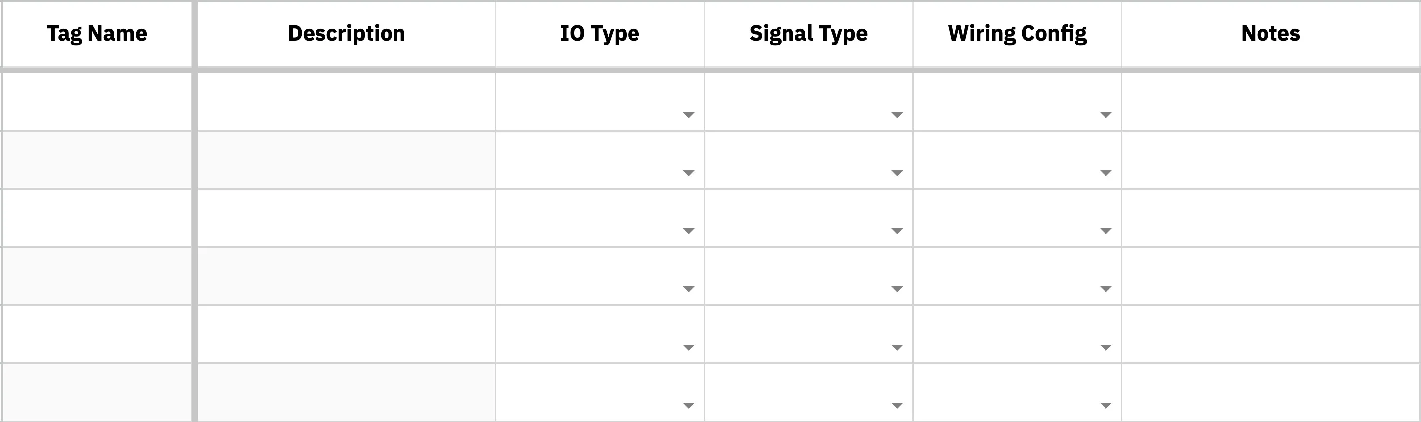
Let's focus on building out the essential fields.
Step 2 - Fill in Descriptions
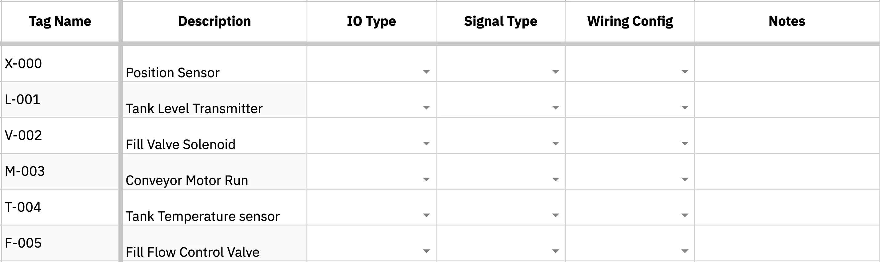
With Blitzpanel's template, tags will automatically generate. If you’re using your own, fill out the tags based on your signal descriptions.
Step 3 - Determine the I/O Type
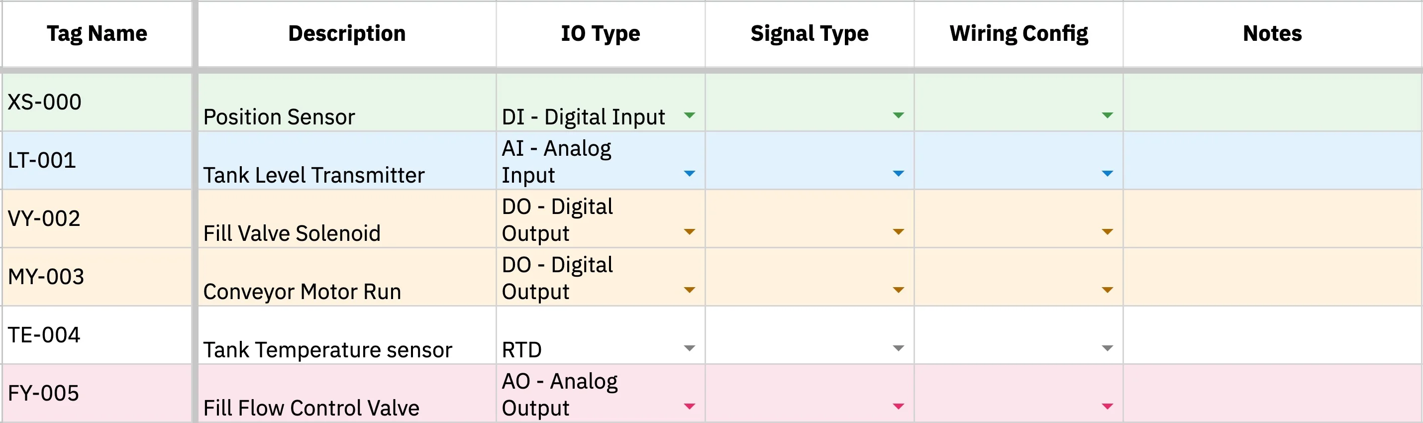
For each row, ask: is this signal coming into the PLC or going out? Then ask: is it on/off or a range? Those two answers usually get you to DI, DO, AI, or AO.
- Digital: Must either be On or Off, 1 or 0, discrete, binary choices
- Analog: Ranges, or continuous values, best for measurement
You might encounter specialized I/O Types: RTD and Thermocouple are associated with temperature sensors. COMM signals are data connections, like ethernet. HSC are high speed sensors where regular DI doesn’t work.
Step 4 - Determine the Signal Type
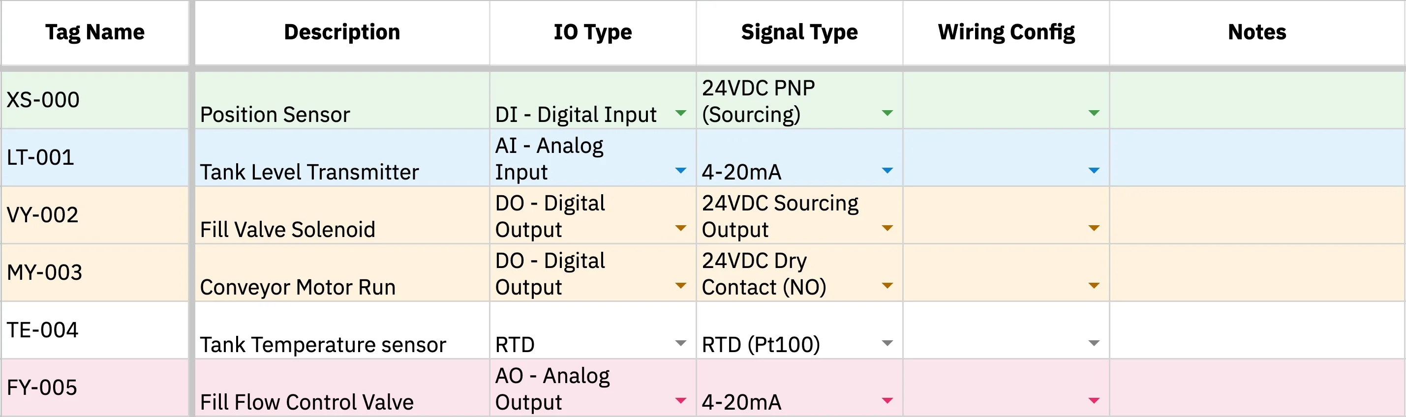
Signal type explains what kind of electrical signal the PLC is dealing with.
To fill this column, check the device datasheet or wiring diagram. Look for terms like 24 VDC, 4-20 mA, 120 VAC, dry contact, RTD, or Ethernet/IP. There are many other signal types, but you don’t need to memorize them all.
If you are unsure, leave it blank and flag it for the panel designer.
Step 5 - Determine the Wiring Configuration
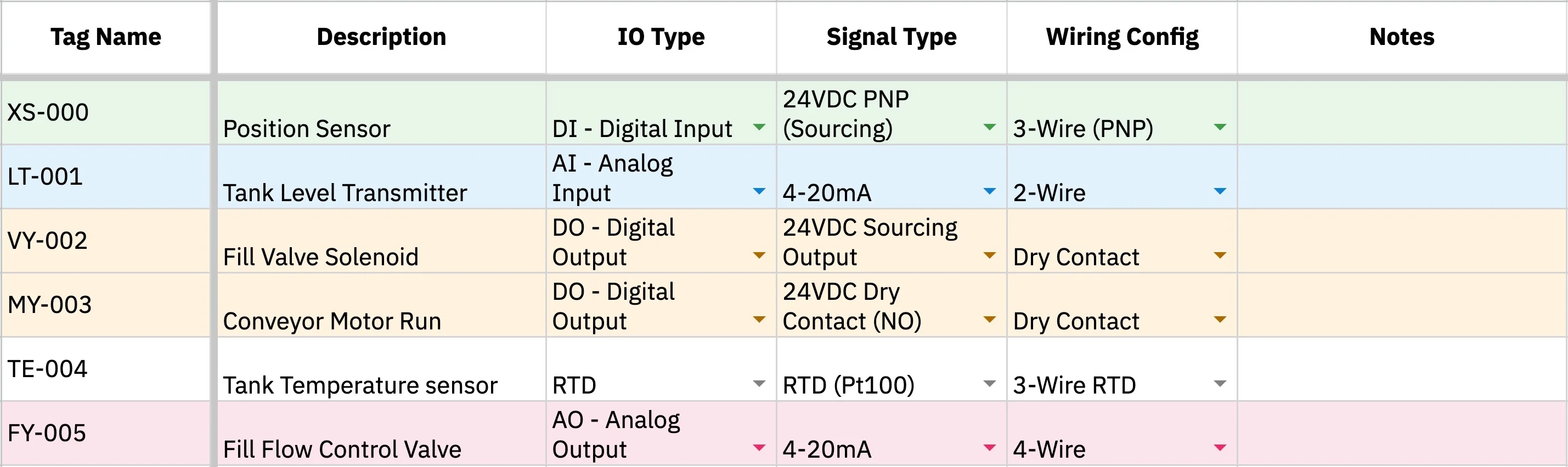
- Does it use two wires for power and signal? That’s 2-wire.
- Does it need power, common, and signal? That’s 3-wire.
- Does it have separate power and signal wires? That’s 4-wire.
- Is it only opening or closing a circuit? That’s usually a dry contact.
- Does the signal need protection from noise? It may need shielded cable.
There are some specialized wires in PNP and NPN, if you’re unsure, leave it blank and consult an engineer.
Step 6 - Add Notes
Keep notes short and useful. The goal is to capture the small things someone might need during design, wiring, testing, or troubleshooting.
Step 7 - Bring Your IO List To A Panel Shop
Once your IO list is filled out, your panel shop will turn that list into a real design!
A panel shop uses your IO list to choose PLC hardware, size IO cards, plan terminals, and understand how every field device connects back to the panel. The person doing this work is typically a controls engineer.
More importantly, they’ll clean up anything you’re unsure about.
If you’re ready for a control panel, start working with Blitzpanel here!
Free I/O List Template
Get started with your I/O list ASAP with Blitzpanel’s free, simple-to-use template.
Compatible with Google Sheets, Excel, etc, and includes a cheat sheet on how to fill in every variable.
Additional help for your control panel project is always available here.
FAQ
Where do I find the information needed to fill out an I/O list?
Start with the device datasheet, wiring diagram, or equipment manual. Look for details like voltage, signal type, wiring style, and output range. If you are unsure, write what you know in the Notes column and flag it for the panel designer.
Do I need to complete every column before sending my I/O list to a panel shop?
No. Fill out what you know and leave the rest blank! The most helpful starting point is a clear description of each device or signal. A panel shop can usually help clean up the missing details, especially if you provide datasheets, drawings, or equipment information.
Can one device have more than one I/O point?
Yes. One device can need multiple signals. For example, a pump may need one output signal to start it and one input signal to confirm it is running. A valve may need a command to open and a separate signal showing whether it is actually open.
What should I do if I do not know whether a signal is DI, DO, AI, or AO?
Ask two simple questions: is the signal going into the PLC or coming out of the PLC? Then ask whether it is on/off or a range. An on/off signal going into the PLC is usually DI. An on/off signal coming out is usually DO. A measured range going into the PLC is usually AI. A controlled range coming out is usually AO.
Why does the panel shop add more columns to my I/O list?
Your I/O list explains what the system needs to do. The panel shop adds build details that help turn that list into a real panel. These details may include cable tags, terminal blocks, wire colors, conductor counts, and other information needed for wiring, testing, and troubleshooting.
When should I start making an I/O list?
Start as early as possible. You don’t need to have every detail figured out. Even a rough list of pumps, valves, sensors, switches, and instruments gives the panel shop a better idea of the project scope.
What happens if my I/O list changes during the project?
This is totally normal. Devices may be added, removed, or updated as the project develops. The important thing is to keep the I/O list up-to-date so the panel design, wiring, PLC program, and testing plan are all based on the same information.
Resources
IO List Template
Get the free IO list template →
Build Your Control Panel
Start a project with Blitzpanel →